Description
TASK 72-00-00-500-002 Engine General – Prepare The Engine For Storage, Storage-002
Support Equipment
| Name | Part Number / Identification | Quantity | |
| 1 | Spray Can with Nozzle Extension | Spray Can with Nozzle Extension | |
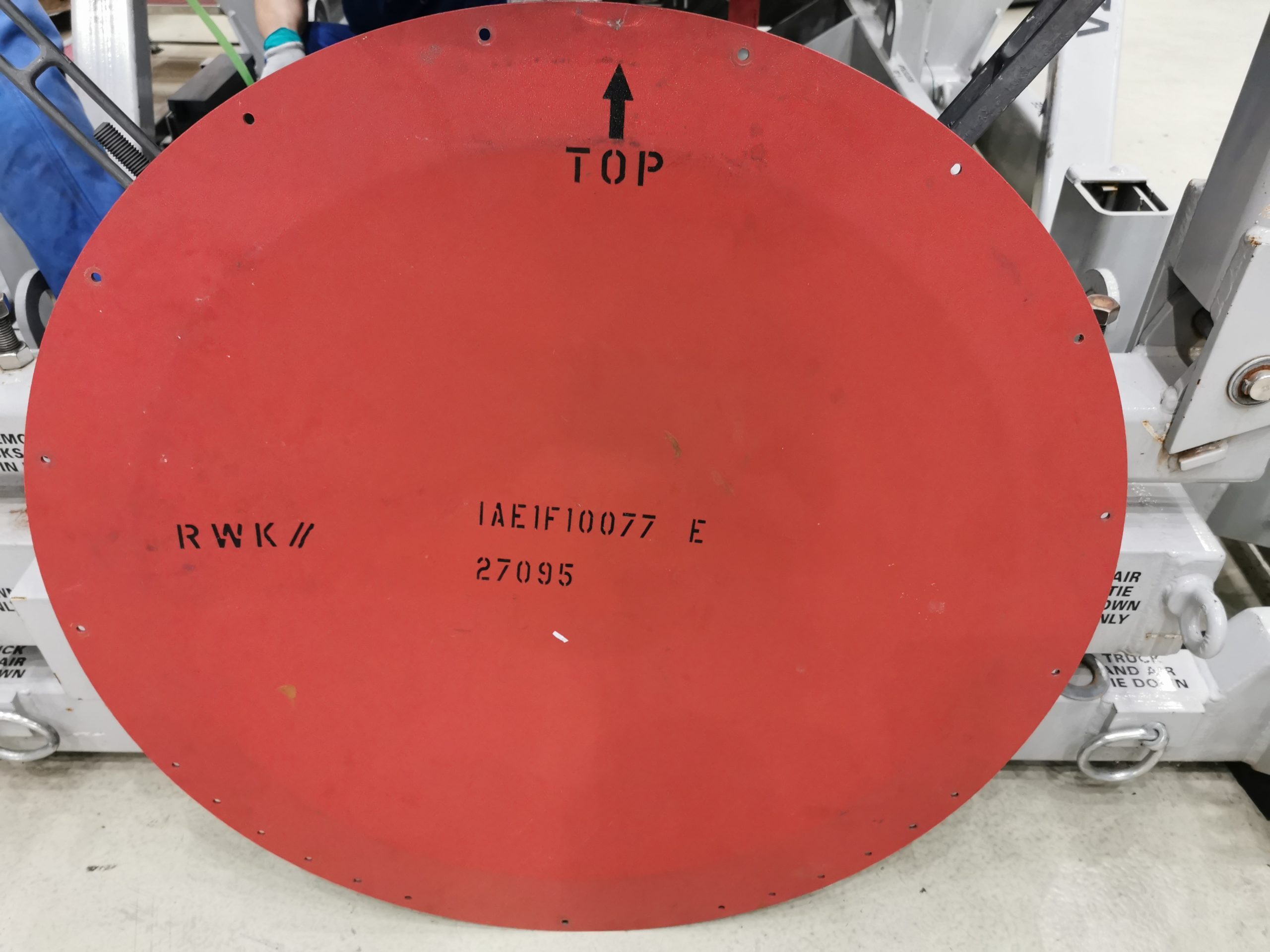
| 2 | IAE 1F10077 Protective cover | IAE 1F10077 | 1 |
| 3 | IAE 1N20008 Protective cover | IAE 1N20008 | 1 |
| 4 | IAE 1N20400 Protective cover | IAE 1N20400 | 1 |
| 5 | IAE 1N20435 Protective blank | IAE 1N20435 | 1 |
| 6 | IAE 1N20436 Protective blank | IAE 1N20436 | 1 |
| 7 | IAE 1N20443 Protective blank | IAE 1N20443 | 1 |
| 8 | IAE 5F10060 Closure kit | IAE 5F10060 | 1 |
| 9 | IAE 5F10351 Shipping cover | IAE 5F10351 | 1 |
| 10 | IAE 5J12080 Rear cover | IAE 5J12080 | 1 |
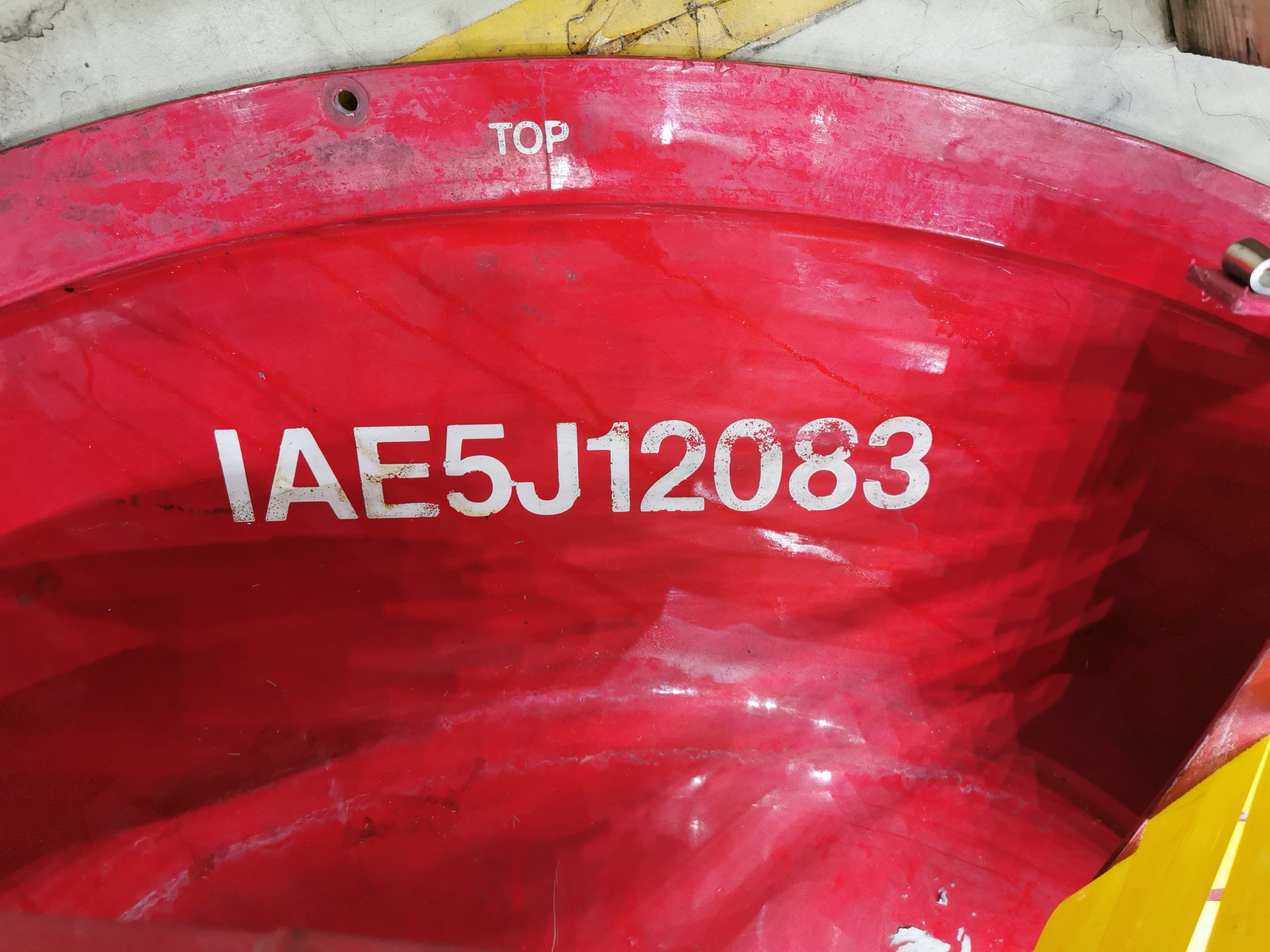
| 11 | IAE 5J12083 Front cover | IAE 5J12083 | 1 |
| 12 | IAE 5J12142 Protective cover | IAE 5J12142 | 1 |
| 13 | IAE 5J13353 Protective cover | IAE 5J13353 | 1 |
| 14 | IAE 5J13354 Protective cover | IAE 5J13354 | 1 |
| 15 | IAE 5J13500 Protective closure | IAE 5J13500 | 1 |
| 16 | IAE 5P16183 Shipping closure | IAE 5P16183 | 4 |
| 17 | IAE 5R18304 Transportation cover | IAE 5R18304 | 1 |
| 18 | IAE 5R18305 Transportation cover | IAE 5R18305 | 4 |
| 19 | IAE 5R18306 Transportation cover | IAE 5R18306 | 2 |
| 20 | IAE 5R18307 Transportation cover | IAE 5R18307 | 1 |
| 21 | IAE 5R18310 Transportation plug | IAE 5R18310 | 3 |
| 22 | IAE 5R18311 Transportation cap | IAE 5R18311 | 1 |
| 23 | IAE 5R18312 Transportation cap | IAE 5R18312 | 1 |
| 24 | IAE 5R18317 Transportation plug | IAE 5R18317 | 1 |
| 25 | IAE 5R18318 Transportation plug | IAE 5R18318 | 1 |
| 26 | Cap | CD-5 | 2 |
| 27 | Plug | ADP-5 | 1 |
SUBTASK 72-00-00-550-058-003 Blank Engine Build-Up Unit (EBU)
1. Refer to Figure 2.
2. Make sure the engine is dry before you attach the blanks.
WARNING
THE AIRCRAFT HYDRAULIC FLUID AND THE VAPOR ARE DANGEROUS THROUGH ABSORPTION AND INGESTION. THE HYDRAULIC FLUID CAN CAUSE EYE, NOSE AND SKIN IRRITATION. DO NOT BREATHE THE VAPOR.
DO NOT GET HYDRAULIC FLUID ON YOUR SKIN OR IN YOUR EYES. YOU MUST USE PROTECTIVE GOGGLES AND GLOVES. YOU MUST OBEY THE MAKERS SPECIAL INSTRUCTIONS.
CLEAN YOUR EYES IMMEDIATELY WITH CLEAN COLD WATER IF HYDRAULIC FLUID GETS INTO THEM AND GET MEDICAL AID. USE SOAP AND HOT WATER TO IMMEDIATELY CLEAN THE AREA OF SKIN TOUCHED BY THE HYDRAULIC FLUID.
CAUTION
REMOVE HYDRAULIC FLUID IMMEDIATELY WITH A DRY CLOTH AND WASH THE AREA OF CONTAMINATION WITH MILD CLEANER, REFER TO THE SPM TASK 70-11-03-300-503. THE HYDRAULIC FLUID USED IN THIS SYSTEM WILL CAUSE DAMAGE TO A LARGE RANGE OF MATERIAL SUCH AS RUBBER, COPPER, DIFFERENT PLASTICS AND PAINT.
Attach applicable blanks to the subsequent positions:
Position 1,IAE 5R18312 Transportation cap 1 off to the fuel return pipe.
Position 2,IAE 5J12142 Protective cover 1 off to the front mount tube.
Position 3,IAE 5R18305 Transportation cover 4 off to the handling off-takes.
Position 4,IAE 5J13353 Protective cover 1 off to the No4 bearing compartment air cooler inlet.
Position 5,IAE 5R18306 Transportation cover 2 off to the cabin off-takes.
Position 6, IAE 5F10060 Closure kit 1 off, use hydraulic pump cover.
Position 7,IAE 5R18310 Transportation plug 1 off to the P2 sense EEC.
Position 8, IAE 5F10060 Closure kit 1 off, use intergrated drive generator cover.
Position 9,IAE 5F10351 Shipping cover 1 off to the gearbox breather vent.
Position 10,IAE 5R18304 Transportation cover 1 off to the ACOC modulating valve.
Position 11,IAE 5J13500 Protective closure 1 off to the ACC duct inlet.
Position 12,IAE 5J13354 Protective cover 1 off to the No4 bearing compartment air cooler outlet.
Position 13,IAE 5R18317 Transportation plug 1 off to the IDG pipe.
Position 14,IAE 5R18318 Transportation plug 1 off to the IDG pipe.
Position 15,IAE 5P16183 Shipping closure 4 off to the EEC cooling manifold.
Position 16,IAE 5R18310 Transportation plug 1 off to the diverter valve.
Position 17,IAE 5R18310 Transportation plug 1 off to the FMU drain.
Position 18,Cap 1 off to the air modulating valve drain.
Position 19,Cap 1 off to the oil tank overflow.
Position 20,Plug 1 off to the core common drain tube.
Position 21,IAE 5R18307 Transportation cover 1 off to the anti-icing bleed.
Blank the fuel pump and oil tank with the blanks from theIAE 5F10060 Closure kit 1 off.
4. NOTE
Blanks from the closure kit that have not been used must be put in the canvas bag and positioned in the storage cover or bag.
Position the closure kit with the engine.
5. Where blanks are not available cover the opening with CoMat 12-013 PRINTED, WAXED, VCI COATEDPAPER. Safety with CoMat 02-040 MOISTURE RESISTANT TAPE, CoMat 02-041 MOISTURE RESISTANT TAPE, CoMat 02-042 MOISTURE RESISTANT TAPE, Moisture Resistant Tape, CoMat 02-044 MOISTURE RESISTANT TAPE, CoMat 02-045 MOISTURE RESISTANT TAPE or CoMat 02-046 MOISTURE RESISTANT TAPE.
6. Blank all the disconnected harness connectors and make a cover with CoMat 12-033 AIR BUBBLE SHEET. Then attach the harness to an adjacent structure to prevent damage.
7. If necessary remove the P2/T2 probe.
8. Blank the P2/T2 probe.
Apply a layer of CoMat 12-033 AIR BUBBLE SHEET to the P2/T2 probe.
Put the P2/T2 probe in a box made of CoMat 12-034 FIBREBOARD BOX or CoMat 12-035 FIBREBOARD BOX.
Attach the box to a fan case strut with CoMat 02-040 MOISTURE RESISTANT TAPE.
9. Remove the pneumatic starter valve.
Disconnect the electrical connector 4005KS-A from the starter control valve.
Hold the starter valve and remove the coupling which attaches the valve to the upper duct.
Remove the starter valve and the seal.
Apply a layer of CoMat 12-033 AIR BUBBLE SHEET to the starter valve .
Put the starter valve in a box made of CoMat 12-034 FIBREBOARD BOX or CoMat 12-035 FIBREBOARD BOX. Seal the box with moisture resistant tape.
Position the box with the engine.
10. Attach IAE 5J12083 Front cover 1 off to the engine inlet.
Use CoMat 12-013 PRINTED, WAXED, VCI COATEDPAPER to make a cover for the engine inlet.
Put the coated side of the VPI impregnated paper to the compressor fan blades and hold with CoMat 02-040 MOISTURE RESISTANT TAPE.
Install the IAE 5J12083 Front cover to the engine inlet.
11. Attach IAE 5J12080 Rear cover 1 off to the fan case outlet.
Use CoMat 12-013 PRINTED, WAXED, VCI COATEDPAPER to make a cover for the fan case outlet.
Put the coated side of the VPI impregnated paper to the rear of the fan case struts and safety with CoMat 02-040 MOISTURE RESISTANT TAPE.
Install the IAE 5J12080 Rear cover to the fan case outlet.
12. Attach IAE 1F10077 Protective cover 1 off to the turbine exhaust case.
Use CoMat 12-013 PRINTED, WAXED, VCI COATEDPAPER to make a cover for the turbine exhaust case.
Put the coated side of the VPI impregnated paper to the turbine exhaust case (TEC) struts.
Install the IAE 1F10077 Protective cover to the turbine exhaust case.
13. Install CoMat 12-033 AIR BUBBLE SHEET on all locations and brackets that can possibly make a hole in the VMI bag or storage cover.

